To learn what are turbochargers, the first thing we must know is what is turbo power?

To carry out complete combustion of fuel oil, it is necessary to provide enough oxygen, which is not in majority in the air quantity. The more air we are able to introduce fuel into the cylinders of the engine, the more power that can be obtained, but the more mass of air necessary to burn, this necessity arises the idea of supercharged engines. The fresh charge enters the cylinder at a pressure much greater than the compressor inlet pressure and thus the inlet temperature will be equally high.
Overfeeding is to establish at the entrance to the engine's cylinders an atmosphere of air with a density higher than normal so that for a given volume of air, that air mass is greater, for it uses a number of accessories, which will differ depending on the type of supercharger used.
The supercharger or turbocharger is essentially a compressor driven by exhaust gas, whose primary mission is to press the intake air to thereby increase the amount that enters the engine cylinders in the intake stroke, allowing it to burn efficiently more amount of fuel. Thus, the torque and the final power can be increased up to 35%, thanks to the turbocharger.
This device has been designed to increase the overall efficiency of the engine. The energy to drive the turbocharger is extracted from the energy wasted in the engine exhaust gas is composed of a turbine wheel and shaft, a compressor wheel, a central housing which serves to hold the rotary joint, bearings, a turbine housing and compressor housing.
The turbine wheel is located in the turbine housing and is mounted on one end of the turbine shaft. The compressor wheel is located in the dcl compressor housing and is mounted at the opposite end of the axis of the turbine wheel to form a comprehensive set rotating.
The set consists of a rotating turbine wheel and shaft together forming a piston ring, a thrust spacer, wheel and compressor wheel-retaining nut. The rotary joint is supported by two bearings lubricated pressure maintained in the central housing by spring rings. Internal oil passages are drilled in the central housing to provide lubrication to the bearings of turbine wheel shaft, the thrust washer, thrust collar and thrust spacer.

The turbine housing is a casting of heat resistant alloy wheel that houses the turbine and provides an entrance flange of the engine exhaust gas and an outlet located axially exhaust gas turbocharger. The turbine housing is bolted to the turbine end of the central housing, thus providing a compact set and free of vibrations.
The compressor housing that houses the compressor wheel provides an ambient air inlet and a discharge outlet of compressed air. The compressor housing is attached by brackets to the end of central housing compressor.
According to the method used to achieve this higher density range (compressed air) can be distinguished:
Volumetric compressors: use some of the torque transmitted by the engine.

Turbochargers and Comprex system:
Both systems use the energy of the exhaust gases.
Volumetric compressors work directly coupled to the engine crankshaft, which transmits the rotation to some part of the volumetric compressor (depending on the type in question), which in turn introduces high-pressure air into the engine cylinders. The key advantage of turbochargers is that the compressor volumetric effects are seen even at low revs the engine. Its disadvantage is that steal some of the engine power to function but then returned with a vengeance. Some of the trademarks of compressors developed are:
Constitution of the turbocharger

The turbocharger consists of three sections: the central housing, the turbine and compressor.
The central housing contains two flat bearings, seals type segment and a separate sleeve. It also has pipes for the supply and discharge of oil into and out of the housing.
The turbine wheel rotates within the casing and is in solidarity with the central axis supported on a rotating journal bearings, coupled within the central housing. The compressor wheel, which is mounted at the other end of the shaft, a turbine with a set of simultaneous rotation.
A turbocharger can rotate at speeds of 120,000 RPM. In some high performance units.
Operation of the turbocharger
Generally speaking there are two types of turbocharger: the pulse and constant pressure. Each has its own operating characteristics, and yet both act the same basic shape.
The turbocharger is mounted on the exhaust outlet flange of the exhaust manifold of the engine. Once started the engine, engine exhaust gases passing through the turbine housing are rotating turbine wheel and shaft, the gases are discharged into the atmosphere after passing through the turbine housing.
The compressor wheel, which is mounted at the opposite end of the axis of the turbine wheel, rotates with the turbine wheel. The compressor wheel sucks in air compressor to housing environment, compresses air and sends it to the blower motor.
During operation, the turbocharger responds to engine load requirements reacting to the flow of engine exhaust gases. Cl with increasing engine performance increases the flow of exhaust gases and the speed and performance from a rotary increase proportionally to sending more air blower motor.
Some engines are equipped with inter coolers to reduce the discharge temperature of the turbocharger air before entering the blower
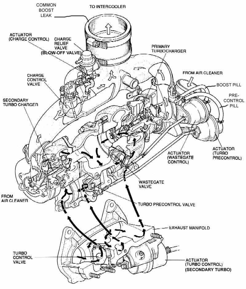
The type turbocharger boost, you need an exhaust manifold specially designed to carry high exhaust pulse energy to the turbine of the turbocharger. This design, with individual branches, as shown in Figure 4.4 avoids interference between the exhaust gas discharge from the various engine cylinders, thereby producing a stream of high-speed drive, which he achieves with other designs.
In some applications, the turbine casing is divided into two zones (momentum divided), thus securing better assistance to prime the whole rotation, the beginning thereof. The design has two chambers in a spiral, instead of one. The term "spiral chamber" is given by the spiral shape of the turbine casing hi, which decreases in volume toward the center, like a snail shell.
Each chamber receives half of the engine exhaust stream, eg a four-cylinder engine, the front two-exhaust gas is discharged into the camera first, while the other two do so in the second.
With the kind of constant pressure turbocharger, exhaust gas from all cylinders flows into a common manifold, where they disappear impulses, leading to a gas inlet into the turbine at a constant pressure.
In both types of turbocharger, exhaust gas entering the turbine spiral shape of a ring (torus), which produces a radial acceleration to a reduced pressure and increased speed on the turbine blades, which are specially designed, of so as to exploit the power of the gas to drive the turbine shaft and compressor wheel attached to it.
The overall compressor design and construction is similar in both the turbocharger boost, and the constant pressure.
The compressor consists of a wheel and a housing that is built into a single spiral or diffuser. Air enters the chamber of the compressor (suction at the turn of it) between the blades of the wheel and is driven by the effect of centrifugal force inside the coil during rotation of the wheel. At this time the air velocity decreases and produces a corresponding increase in pressure. As the air rises around the spiral, its speed is reduced and the pressure increases with the diameter of the cross section of the chamber.
In summary, the supercharger provides a quick impulse type excitation of the rotary joint, due to the rapid succession of pulses of exhaust gas on the whole turbine. It is primarily used in automotive applications, where it is important response acceleration.
The constant pressure turbochargers are mainly used in large diesel engines, bulldozers and marine applications where throttle response is not as critical.
Carburetor-fed engine, depending on where you put the supercharger system can distinguish two cases:
Placement of the turbocharger
Carburetor-fed engine, depending on where you put the supercharger system can distinguish two cases:
Carburetor Blower: The carburetor is located between the compressor and the intake manifold. Thus, the air entering the compressor is clean air directly from outside.
Aspirated carburetor: the carburetor is mounted above the compressor so in this case what is a compressed mixture of air and gasoline.
The latter system was most often used in the first applications of overfeeding, in its simplicity and because it provided an air-fuel mixture temperature lower than the blowing system.
However aculeate greatest use of blown carburetor system as this system allows the use of a heat exchanger or inter cooler. Diesel or gasoline engines fueled by injection this classification makes sense because the fuel injectors are always placed after the supercharging system
Intercooler system

The Intercooler system consists of a heat exchanger which introduces the air leaving the turbocharger to cool before feeding it into the engine cylinders.
On cooling the air reduces the density of it so for the same volume of the cylinder can introduce more air mass and thus improve engine performance.
Advantages Of Turbocharging

Since the turbocharger is activated by the energy of exhaust gas, which discharge to the outside is wasted, a turbocharged engine offers many advantages over the conventional type. Among them we can highlight:
Increased power to weight ratio
A turbocharger can increase power and torque of a diesel engine by 35% over the conventional version. Thus, turbocharged four or six cylinders, smaller, you can perform the work of another major, such as a conventional V8.
Reduced engine noise
The turbine casing acts as a set of noise absorption of the engine exhaust gases. Similarly, the compressor section inlet reduces noise produced by the pulses in the intake manifold. As a result, a turbocharged engine is usually quieter than other conventional, though generally perceived characteristic whistle when the engine is under load or accelerating.
Fuel Economy
A turbocharged engine has a higher volumetric efficiency than conventional, with which it achieves more complete combustion, which results in lower fuel consumption.
Smoke Reduction
The engine turbochargers supply the extra quantity of air in the operation at medium and high speed, resulting in a phase of combustion more efficient and clean, which reduces the production of smoke.
Disadvantages of Turbocharging
Reduced power at low revs
When it has only recently stepped on the gas and therefore a system of laps in, the exhaust gases are significantly reduced and this causes the turbo just work. The engine response is not very bright then unless you use a conveniently short way to increase the engine speed..
The maintenance of the turbo is more demanding than a naturally aspirated engine.
Turbo engines require a higher quality oil and oil changes more frequent, as it is subjected to harsher working conditions have to lubricate the bearings of the turbine and compressor often at very high temperatures.
Turbocharged engines require better materials and lubrication and cooling systems more efficient.
The turbo in the future
One of the most needed improvements in turbocharged engines has to do with his performance at low revs. Advances in this section leads to an improvement in the delivery of the turbine, together with increased flows and performance of the compressor.
To achieve this, one of the latest techniques used is the use of variable inlet turbines. This technique improves both the maximum values of torque and power as the answer to any regime.
Weight is another aspect to improve. In their latest models, Garrett (turbochargers manufacturer) has come to reduce weight by over 50% of the T3 model 7 kg to 3 kg of GT12.
The turbo petrol engine is another need increased reliability at high temperature. A full charge is good for 1000 ° C in the turbine and the most common material, called Inconel, undergoes changes in its structure from these grades. In the future austenitic stainless steel is used for surround, expensive today, but secured by its use in competition.
Compressor COMPREX
The Comprex type compressor uses energy transmitted by direct contact between the exhaust and intake by pressure waves generated depression in intake and exhaust processes. The results from Comprex quite large, and is driven by the crankshaft via a belt. For both reasons to choose placement opportunities are extremely limited.
- Gas chamber.
- Rotor.
- Transmission-belt crank-COMPREX.
- Manifold.
- A mixture of admission.
- A mixture of pressure.
- Engine exhaust gases
Comprex system, like turbo systems, harnesses the energy of the exhaust gases. Its main advantage is that it responds more quickly to changes in engine load, so it will behave more cheerful.
The main disadvantages of this system are:
- Rates two or three times higher than the equivalent of a turbocharger.
- Presence of a shrill whistle during acceleration.
- High temperature gas admission, having been in contact with the walls of the exhaust gases.
- Axial type turbochargers.
The axial turbochargers operate as fans of the same type, but typically are built in several stages. Each crown fixed blade diffuser plays the role of precedent for the rotor and distributor to the next. Its general constitution reminds us of the jet turbine.
The compression ratio per stage is significantly lower than that for a centrifugal compressor. With a circumferential speed of 200 to 250 m / s can be obtained, for air, a compression ratio of 1.08 per rotor, approximately.
The correction of the profile of the blades is of paramount importance, that profile should be considered in accordance with the laws of fluid mechanics. Indeed, the centrifugal force does not allow, as in the case of centrifugal compressors, the adhesion of the fluid with the wall of the blade, a small deviation of the inclination of the latter leads to the formation of eddies, the launch of the vein aureolic and desperado compressor. That is, the best performance corresponds to a varying flow margin very narrow, as on the other hand, the characteristic curve of pressure-flow has a steep, axial compressors are only suitable for applications where, for a speed constant, the flow is well determined.
However, certain axial compressors are equipped with a device for regulating the orientation of the blades, is turbocharged stationary, or with the running machine, which allows adaptation to the conditions of use.
The route taken by the fluid is much more straightforward than in the case of centrifugal compressors, which allows a building with smaller size and lower weight can be obtained in normal yield a significant increase optimum performance can reach the adiabatic 85%.
Axial compressors are used in the cycle gas turbines and turbojet aircraft, its employment. Its characteristic is the use of turbochargers refrigerated for large volumes (300 to 3000 m3/min.) And weak pressures (2 to 3 Kg/cm2 effective) for air injection in blast furnaces. Also, mixed compressors are built in the early stages which are of the remaining axial and centrifugal type.
Ideal cycles and processes
Although the combustion engine does not work according to a thermodynamic cycle cycle thinking is still a very useful file to show the effects of changes in operating conditions, to indicate the maximum performance and to compare one type of combustion engine with one over another.
When a hypothetical cycle assumes that the working fluid is air only, is called a cycle of normal air. It is considered that the heat is supplied directly to the cycle or rejected by him ignoring heat losses, while the calorific value of air is estimated to be constant.
Eaton Compressor Roots 1
This is a pure machine movement, which is not compressed air. The effective filling pressure is not created until the intake manifold.
This simple version with two rotor blades creates a relatively low pressure, and further creates very slowly with increasing engine speed.
The power input is located for an overpressure of 0.6 bar and maximum air passage, at 12.2 hp. Roots compressor performance is not very high and it gets worse with increasing engine speed. The supply capacity exceeds 50% only in a very limited range. Compressed air is extremely hot.
Eaton Compressor Roots 2
Like the previous compressed air either internally, however the excess load, under the same conditions, peaks higher.
The absorbed power is at only 8 hp and air temperature rises less. The performance of this compressor is over 50% in a higher range.
Volumetric rotary piston compressor Wankel: Its operation is similar to the roots, but vary substantially geometry. This will greatly improve the properties.
The pressure is reached is high. The power input for a pressure of 0.6 bar and maximum air flow reaches 8.2 hp. The air temperature does not rise much..
The yield is above 50% capacity and average circulation in a narrow range even exceeds 60%.
Propeller Sprintex Compressor
This compressor manufactured in Scotland has a high energy consumption for low supply capacity, the highest in nearly 11 hp. The cause seems to lie in the journal bearings of the compressor Sprintex aided by the internal friction rises too high air temperature. Performance is not very good, and only with high pressure and a high degree of air flow is about 50%.
Piston Rotary Compressor
This compressor has a kinematic relationship with the Wankel engine. A three-blade rotor describes a circular path in a rotating drum with four cameras. The cameras in their rotation they change their volume and thus the air is compressed within the compressor.
Energy consumption is very low also in part load, between 2.7 and 8.2 hp. The temperature rise is small. The performance of the compressor is over 50% in a wide range of average capacity of supply.
Piston Rotary Compressor KKK
It is a modification of the Roots compressor. The rotor turns a drum that surrounds it, it also rotates on its part. The creation of the load pressure and air flow is very fast in the KKK. The power required to achieve high pressure and high flow is relatively low, with values approaching the 8 hp. The air heats up very little overpressure. KKK compressor performance is very good and in a range around 50% and a range smaller than 60%.

G De Volkswagen Compressor
It differs from other models mainly because it is composed of elements in rotation to get the circulation. The compression of air in through the spiral follows an oscillating movement of the inner piece. The supply of the compressor characteristic G satisfies the requirement of rapidly building pressure. A high flow capability is coupled here with a low power consumption, as losses are very small friction in the bearings of the compressor G. The performance achieved in certain ranges of loading, maximum of 60%.
G Compressor Volkswagen is no longer used, and has been incorporated into some engines W. Polo, Golf and W. W Passat for less than a decade.
There are basically two standards of Digital Terrestrial Television, an American (developed by the ATSC) and one European (developed by ETSI).

Technical review to the American system
This system is based on an 8-VSB modulation. It is a vestigial sideband system (like an analog system) based on an 8-QAM modulation that extends to 64-QAM with Trellis coding.
A third digital terrestrial television standard, Japanese, known as ISDB (Integrated Services Digital Broadcasing), maybe minor or previous deployment.
The European System of Digital Terrestrial Television Broadcasting
The European system is based on the specifications of DVB-T (Digital Video Broadcast-Terrestrial), carried out by ETSI (European Telecommunications Standards Institute), and included in the document ETS 300 744, March 1997. This standard has been adopted by European countries and by countries from outside, like Australia, Brazil or India.
The following describes briefly the most relevant technical aspects of DVB-T, in its application to systems of digital terrestrial television broadcasting.
As stated in the rule itself, the DVB Project (Digital Video Broadcast) is a consortium of public and private organizations in order to establish the framework for the introduction of digital television services based on MPEG-2. This is proposed to address real needs in this area taking into account the situation and state of the markets and the economic circumstances of both the consumer electronics industry as television broadcasting. The system defines the modulation schemes and channel coding for terrestrial broadcasting services LDTV (Limited Definition Television), SDTV (Standard Definition Television), EDTV (Enhanced Definition Television) and HDTV (High Definition Television).
The development of DVB-T was based on a set of user requirements produced by the Commercial Module (Commercial Module) of the DVB Project. DVB members contributed to the technical development of the DVB-T through DTTV-SA (Digital Terrestrial Television-System Aspects), Working Group Technical Module (Technical Module). European projects like SPECTER, HD-DIVINE, HDTVT, DTTB, and other organizations developed hardware and system results, which were reported to DTTV-SA.
One of the main features of DVB-T is the use of MPEG-2 packets, which implies that it is transportable any information which is digitized (video, audio, data, multimedia, etc ...). In addition, the specifications are included in a set of return channels for users to interact with digital services received (see section on user receivers).
The system is defined as a functional block that performs the task of adapting the television signal base-band output. MPEG-2 transport to the characteristics of terrestrial transmission channel. In the figure below you can see the system blocks
System Protection Schemes
As you can see, the system consists of a large number of blocks relating to protection against errors, leading to the modulation signal for transmission over the air interface. The diffuser system input signal is MPEG-2 packets, so that the output in the receiving equipment, you also have this format. Without going into details are described briefly and interlaced encoding schemes before modulation:
* The coding system uses outer Reed-Solomon (RS (204.108)) to protect against errors and outer convolutional interlaced to disperse the packets, and thus protect the transmission of burst errors (a large number of consecutive errors, package makes the unrecoverable).
* It uses internal convolutional coding (punctured Convolutional Code), as well as internal interlaced.
Modulation scheme. Networks
Following the above schemes to protect against adverse propagation conditions, is passed to the description of the modulation scheme employed. We concentrate more on it, it can assume a key part in implementing these services. Indeed, as is well known, one of the most expensive, and therefore of greater requirement on a system optimization is via radio frequency, spectrum. Because of this lack of band, try to use all available technology at the lowest possible cost to optimize the spectrum band to use. Here is already one of the key points in the discussion of the appropriateness of using television systems via radio broadcast in front of the cable cast.
In principle, the main argument for the defense of cable television, from a technological standpoint, the big band is available in its transmission, especially in fiber optic systems. This huge capacity inherent in cable systems will be his main defense argument against their lack of mobility (not necessarily of ubiquity) of television receiving equipment. Indeed, it is unthinkable to drag a fiber optic cable when you want to watch TV from inside a vehicle on the streets of a big city, although it is arguable whether or need for this type of service, when going driving for example.
Thus, it is seen as a new generation system of this type has to present a coding and modulation scheme is very robust and consistent in order to provide the desired services with the desired qualities, knowing the amount of information that may require the transmission of television, especially high quality, and the narrow spectrum that may be available.
The modulation scheme employed is the COFDM (Coded Orthogonal Frequency Division Multiplexing). The COFDM modulation scheme is particularly suited to the needs of terrestrial broadcast channels, mainly for the following reasons:
- Can withstand high levels of multipath (found mainly in large urban centers, market potential of digital terrestrial television), with high dispersion of delays between the signals received. This also results in single frequency networks (SFN: Single Frequency Networks), where we can speak of "artificial multipath". In reality, the legislation supports DVB-T networks use both Multifrequency (MFN: Multi-Frequency Networks), in which planning is similar to that of existing analogue systems.
- COFDM also supports co-channel narrowband interference, such as that produced other terrestrial analogue services. It is also important to anticipate that there will be a time of transition in which contain a number of television broadcasting services, including analog, to a total deployment of digital systems, both terrestrial and satellite, in addition to cable services. Therefore the technical planning, in point of frequency planning and electromagnetic compatibility has to take into account this fact.
In COFDM modulated data in a large number of carriers at low speed, using FDM techniques. The reason for using multiple carriers actually come from the fact that high levels of multipath. As discussed, cities and urban centers could, in a first approximation, the main market for these networks. The reason is that it is in these large groups of buildings and structures where radio systems could charge via advantage over cable systems, which at first glance appear as its main competitors, due to the great difficulty, especially economic and logistics involved wiring a city.
Multipath phenomena are also particularly augmented by the widespread use of the known set-top TV antennas. The basic idea is that if delays are expected higher the signal, the multipath effects, it has to have a symbol duration much larger than those tolerable delay for them, which seems more appropriate to employ many low-speed modulated carriers that one can speed alone. This effect is also noticeable in the frequency domain, seeing as multipath causes selectivity in frequency, avoidable (carrier to carrier, within a narrow band channel), with narrow bandwidths.
However, it is conceivable that although the symbol period has become much larger than the largest of delays for multipath, there is still interference between symbols (ISI), as shown in figure (right). To avoid this small fraction of time in which there is interference between symbols, what is done is to insert a guard time.
Technical Issues in the Implementation of DTT Network
Transmitter Installation
In principle, the digital television transmitters used the current locations of analog television transmitters, which could be reused much of the infrastructure currently available. In some situations require a new antenna, if available outside antenna to be employed should be noted that digital signals should be combined with high power current analogue signals (at least during the transition analog-> digital) either the whole should be passed by a multichannel amplifier, which would raise problems of filtering and non linearities.
Primary Distribution
It requires a primary distribution network to transport packets from MPEG-2 television studios to re-multiplexers centers (regional variations in programming) and to centers transmitters.
It considered several possibilities, among which include fiber optic networks, PDH (Digital Hierarchy) or SDH (Synchronous Digital Hierarchy), ATM or satellite. A complete network probably consist of a combination of the possibilities discussed.
Equipment User Receivers
Probably one of the most critical requirements for adopting a new standard is the availability of equipment that support it. Indeed, a key factor in the successful implementation of a DVB-T system is the system that is attractive and new services and benefits it offers over the earlier analog systems, which is largely marked by the possibility of simple receivers have on the one hand, and versatile and offer a variety of other services.
Among the advantages over existing analog systems emphasize:
- Better use of bandwidth, which leads to the possibility of offering more channels and / or better quality.
- Related to the use of spectrum, there is the possibility of conditional access (Conditional Access), which is reflected in new forms such as subscriptions, Pay-Per-View, etc, based on user interactivity.
- Best of both image quality and audio.
- Ability to allocate part of the spectrum data or images, allowing the user access to other information (such as player statistics at a sporting event).
On the subject, it should discuss the enormous additional specification work has been done in England (as a pioneer and probably reference) in order to maximize interoperability while maintaining the compatibility with DVB. Much of this work was intended to specify an API (Application Programming Interface) for interactive services
Set Top Box
The STB is the receiving terminal to be installed in homes for the reception of DTT. In this respect are fundamental Digitag forums (Digital Terrestrial Action Group) and VALIDATE. Digitag evaluates the characteristics required to meet the user's receiver. VALIDATE is the working group that validates all the experiences of Digital Terrestrial Television, as to the compatibility of equipment from different manufacturers.
STB designs continue to add new functionality and finding ways to reduce costs. One achievement is the development of an advanced platform that enables streaming video on demand (DVD) and other applications via DVB terrestrial, and represents a breakthrough in the convergence of the recipients of the homes. The development of advanced STBs, enables low cost solutions and ease of use of DVD, digital interactive TV (with teletext more advanced functions), and MPEG-2 applications such as PPV (Pay Per View or Pay per view) and video on demand providing new levels of interaction.
Multimedia Home Platform
In 1997, the DVB Project extended its reach to the Multimedia Home Platform (MHP), which will consist of the terminal access from home (STB, TV, PC), peripherals and digital home network.
This platform will enable users to access interactive services and Internet (e-mail, chat). The platform will increase the capacity of the STB allowing to provide interactive services. The platform is a software solution that makes television more useful, fun and service to households. In addition, it will create new economic opportunities for network operators and content providers, hardware and software. There are considerable possibilities for the devices, from advanced STBs to the integrated high definition televisions. A crucial role in integrating the API (Application Programming Interface).
DVB standards offer great opportunities for manufacturers of receivers. It is likely that the initial products differ substantially. The possibilities are enormous users as they choose to receive a combination of enhanced content, high quality images and new services. DVB specifications you manage multiple methods of transmission. One possibility for users is receiving combined terrestrial / satellite, although it is unlikely at first.
Silicon is the essential factor of an electronic device. An electronic chip is made up of silicon wafer. But silicon is one of the rarest metals on the earth. It is difficult to extract pure silicon from its ore quartzite. The cost of production of electronic chips has gone to a high value because of this high cost of production. So it will be advantageous if an alternate element is used in place of silicon.
Silicon chips are expensive to make. So in order to make cheap chips plastic can be used. Scientists in Cambridge University have come with this revolutionary invention that will change the future of electronics. With this technology the cost of production of electronic goods will decrease and will revolutionize electronic industry and products. It will be beneficial for the common man because electronic goods will be available at low cost. There are some advantages of plastic chips over silicon chips. Lighter in weight and easy availability are among them.
Almost all the properties of silicon chips can be maintained in plastic chips also. This is one of the major advantages of using plastic chips. Also this will make the size of components smaller. We can print circuits on cloths and small devices that will make things extra small and smart.
The materials used for making plastic chips are Polythiophenes. Polymer materials are used for the construction of chips. For creating insulation polymer materials like PVP (polyvinyl phenol) is used. For active switching, semi conducting polymer materials are used. The double bond present in the polymers is providing the necessary electron for conduction. Also dopants added will determine the material is p type or n type. P type doping can be made by adding iodine and n type material can be made by adding lithium.
The manufacturing of plastic chips can be done by two methods.
1. Photolithography

This is the conventional manufacturing process
2. Direct printing of polymer transistor circuit.

In this method conducting surface is made by spraying tiny globular plastic into the surface like paper or cloth etc. inkjet printing technology is used for the printing purpose. Advantages of using this technology are that the time required for the printing process is less when compared to other manufacturing processes. Also this will reduce the cost of production.
All resources present in the earth are perishable. Sunlight is the only renewable recourse that will last for the coming decades. This can be tapped using solar panels. But this method has a disadvantage because the availability of sunlight is not uniform throughout the day. Also it varies as weather changes. But in space availability of solar power is uniform. There will be no obstruction blocking solar power in space. So it will be advantages if the power generated in space can be transmitted to the earth. But there is no such technology for transmitting power through space or air.
I am going to tell one of such technology which will enable the transfer of energy through vacuum. From 1070 onwards scientists have been doing experiments for developing a method for transmitting over through air. They began to think that if they are capable of transmitting the power generated in the solar panels of satellites to earth. They decide to develop a method to beam the power generated in the satellites to earth.
The satellite will be placed in a geo stationary area where the position of satellite doesn’t change. The satellite will be loaded with large number of solar cells. These cells generate electricity without any moving part. One and only moving part in the satellite will be antenna which tracks the ground station. With solar panels low voltage is produced. In order to avoid the ohmic loss in conductors super conducting transmission line is used to transmit the signal to the beamer. In the earlier stage the generated electricity will not be beamed to the earth. They will be used for powering space explorating vehicles by beaming the power generated in space stations. Power of about 20-50 KW is possible to transmit between the vehicles by laser transmission or by microwave communication. A microwave of low mass will be used for this purpose.
The processes in power transmission are the conversion of DC power to beam and the reconversion in the receiver.
The basic parts of the device will be
1. DC to microwave converter.
2. Beam generating antenna
3. Receiver and reconverter.
PROPERTIES OF BEAM POWER TRANSMISSION
1. No material is required for power transmission.
2. Speed of transmission of energy will be equal to that of speed of light.
3. Both bi directional transfer of energy is possible.
4. Energy loss will be less because they are transmitted through vacuum
APPLICATIONS
1. Satellite to earth power transmission.
2. Cellular power transmission.
3. Aircraft power supply.
4. Industrial applications.
5. Inter space vehicle power transmission
Communication and computing are closely related to each other. In an enterprise it will be the most important factor which is to be considered. While considering about large enterprises it will be difficult to transfer data by humans. Ti will be more efficient if a proper communication method is adopted. Wired transmission can be used for this purpose. But it will not be possible if the cost of wiring is immense. So in order to avoid this we can adopt RF communication method. In this article let us know about a new communication method which has larger bandwidth compared to older technologies.
Different communication methods can be classified based on the speed and data handling capacity. The latest technology which provides greater speed is the Wi-Fi. A new technology called the Wimax has been developed to increase the speed of Wi-Fi. The recent invention in the communication field is the Ultra wide band transmission. The characteristics of these transmission methods are
1. It have 25% more data handling capacity than Wimax
2. 1 giga bits per second speed can be achieved
3. Less power is required
4. Higher performance than any other existing technology
In the past few years the mobile communication the growth of mobile communication field is rapid. Day by day the new technologies that served our needs are becoming outdated. Need for better technology is becoming more. Ultra wide band will be a revolutionary concept in the mobile communication field. It will also find place in military communication fields and many other fields.
This technology is used for the transmission of digital data in the format of ones and zeros. This uses low energy and lesser duration for transmission of each signal. Burst method is used for the transmission of symbols in RF waves. There is no use of carrier in UWB transmission method. Ones and zeros are directly transmitted. As a result of this the range of this communication is about 15-100m.
UWB is entirely different from RF communication. In the RF transmission wave transmitted are continuous. Let us see an example for understanding this easily. If a man watering the plants moves the pipe in up and down motion what will be the motion of water coming out of the pipe. This will be the RF communication.
While in UWB let as assume a man watering a pipe is closed the pipe with his hand and releasing it at particular interval will seems like water is fired from the pipe. This is the concept of UWB. Very short pulses fired in the time interval of nano seconds will cover a wide area. When the duration of each symbol is varied we can represent the ones and zeros.
UWB wide band transmission can be used to replace the existing communication protocol called the Wi-FI or 802.11 and short range Bluetooth communication. The current fastest communication protocol is the Wi-Fi which is offering a speed of 11 MB/s. this is the minimum speed. It can get up to a maximum speed of 50 MB/s. but the UWB transmission can get up to a speed of 100 MB/s. this speed is the initial speed that can be attain by the launch of UWB. This speed will increase in the future.
More Articles …
Subcategories
Web Hosting
Web Hosting is a service offered by web hosting providers to the individuals and organizations to make their websites accessible on the internet. Depending on the requirement, one can avail different types of web hosting such as shared hosting, dedicated hosting, virtual private hosting, cloud hosting etc.
Page 147 of 193